Vertex vs Fragment Shaders in the Graphics Pipeline
Shaders are small programs that run on the GPU as part of drawing a scene. Some decide where geometry appears on screen, while others decide what that geometry looks like once it is drawn. The first useful distinction in that process is between vertex shaders and fragment shaders. A vertex shader runs once for each vertex in your mesh, while a fragment shader runs for the fragments generated inside the triangle coverage on screen, roughly one per covered pixel sample. Those two stages do different jobs and run at very different rates, which explains much of the behavior, cost, and visual output you see in real-time rendering.
This article builds a concrete model of where each stage runs, what data it reads, and what data it produces. It starts with the vertex-versus-fragment split because that is the foundation for the rest of the graphics pipeline. Later, once that baseline is clear, we place geometry, tessellation, and compute shaders in context.
Pipeline Position and Data Flow
Most real-time 3D engines follow a rasterization pipeline, meaning they start with triangle data and turn it into the 2D image you see on screen. In that process, vertices enter first, then become primitives such as triangles, then rasterization converts those triangles into fragments, and finally the surviving results are written into the framebuffer, which is the image buffer holding the current frame before it is displayed. So the most important question is: what does each stage receive as input?
- Vertex shader input: one vertex at a time (position, normal, UV, tangents, custom attributes)
- Vertex shader output: transformed clip-space position plus per-vertex values that will be smoothly interpolated across the triangle, such as color, normals, or UVs
- Fragment shader input: those interpolated values for each fragment plus textures, uniforms, and material parameters
- Fragment shader output: one or more color/depth values written to render targets
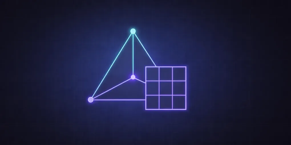
Drag the triangle corners and switch focus between the stages. The main comparison is the important one: a single primitive triggers only a few vertex shader invocations, but can expand into many fragment shader invocations once it covers screen space. The optional-stage view then shows where tessellation, geometry, and compute fit relative to that main path.
In the optional-stage view, tessellation and geometry should both be understood as extra processing that happens before rasterization, not between rasterization and the fragment shader. Compute shaders are separate again: they are GPU programs, but they do not sit on this triangle-to-fragment path at all.
A practical way to remember this is to track where count explodes. A mesh may have tens of thousands of vertices, but a full-screen draw can touch millions of fragments. Because fragment count is often much larger, expensive math in fragment shaders usually costs more frame time than the same math in vertex shaders.
Vertex Shader Responsibilities
A vertex shader is usually responsible for geometric placement. Its most common job is multiplying each vertex position by model, view, and projection matrices. It can also prepare values for later stages, such as world-space normals, texture coordinates, or effect-specific data like a mask value, a blend factor, or a direction vector that the fragment shader will use later.
Mathematically, the canonical transform often looks like this:
Here, [x,y,z,1]^T is the original vertex position written in homogeneous coordinates.
M is the model matrix, which places the object in the world.
V is the view matrix, which expresses the scene from the camera’s point of view.
P is the projection matrix, which maps that camera-space position into clip space so the GPU can continue toward screen-space rendering.
The important detail is not the formula itself, but the execution rate. If your model has 20,000 vertices, this shader runs around 20,000 times for that draw call. It does not run for every pixel on screen.
In the playground below, the gray triangle is the incoming vertex data and the blue triangle is the transformed output after a simplified transform chain. Change rotation, scale, and translation and watch how output vertex positions move in normalized device space.
| rot=18deg scale=1.10 tx=0.22 ty=0.08
One practical consequence of this stage split is that vertex shaders are good at shaping and preparing geometry, while fragment shaders are better for fine image detail inside each triangle. If you push pixel-like appearance work into the vertex stage, the result usually looks blocky or unstable because vertex outputs are only known at the triangle corners and then interpolated across the surface. Interpolation is useful, but it is not equivalent to true per-fragment computation.
Fragment Shader Responsibilities
After primitives are rasterized, the GPU generates fragments. Each fragment has interpolated varyings from the vertex stage. Now the fragment shader decides the visible surface appearance: base color, texture detail, lighting response, transparency logic, and sometimes whether a fragment should be discarded.
This stage is where materials become image detail. If you sample a texture, combine normal maps, compute BRDF terms, apply fog, and blend layers, that work usually happens here.
In the interactive example, each fragment inside a triangle receives interpolated color and UV data. Then a shader-style process blends texture and vertex color, applies a simple Lambert lighting term, and can drop fragments below a threshold (similar to alpha-cutout logic).
| alpha=0.55 discard=0.20
Notice what changes smoothly across the triangle: not the original vertex values directly, but interpolated values. That interpolation step is one of the core reasons the vertex and fragment stages are paired. The vertex stage prepares data endpoints, and the fragment stage uses continuous values between endpoints to compute final appearance.
Direct Vertex vs Fragment Comparison
The fastest way to compare these stages is to ask the same four questions for both.
-
How often does it run? Vertex shader: once per vertex. Fragment shader: once per fragment.
-
What is the main purpose? Vertex shader: geometric transformation and varying setup. Fragment shader: final shading and output color/depth.
-
What data dominates its input? Vertex shader: mesh attributes plus transform uniforms. Fragment shader: interpolated varyings, textures, lights, material uniforms.
-
What performance pattern is typical? Vertex shader: scales with geometry complexity. Fragment shader: scales with screen coverage and overdraw.
These differences imply practical optimization rules. If an effect can be approximated with per-vertex math and interpolation, it can be cheaper. If accuracy must be pixel-precise (specular response, normal mapping, fine procedural detail), it belongs in the fragment stage even if cost increases.
Common Mistakes in Stage Selection
One frequent error is pushing too much logic into fragments without considering coverage. A full-screen post-effect at 4K can execute many millions of shader invocations per frame. Another error is pushing appearance logic too early into vertices and then wondering why detail collapses on large triangles.
A simple decision process helps:
- Does this computation define object placement? Put it in vertex.
- Does it define pixel-level appearance? Put it in fragment.
- Does it need neighboring pixel information from already-rendered data? Often this means a later post-process pass, possibly compute.
That process is not perfect, but it avoids most architectural mistakes in real-time rendering code, especially once you compare it with techniques like ray marching with signed distance fields, which sit outside the standard triangle-raster path entirely.
Other Shader Types in Context
Geometry Shaders
Geometry shaders run per primitive after the vertex stage. They can emit new primitives, so they are useful for specific effects like layered shadow map outputs or line expansion. However, they are often avoided in performance-critical paths because they can become a throughput bottleneck. Many modern engines prefer alternatives such as instancing, mesh shaders (on supported APIs), or compute-driven generation.
Tessellation Shaders
Tessellation is split into control and evaluation stages. It subdivides patch primitives to add geometric density on the GPU. This can improve curved surfaces and displacement mapping when screen-space detail demands it. The tradeoff is increased complexity and hardware/API constraints, so many teams use it selectively.
Compute Shaders
Compute shaders are not tied to rasterization. They execute general-purpose GPU kernels over thread groups and are widely used for simulation, culling, particle updates, clustered lighting preparation, denoising, and post-processing. In modern renderers, compute often cooperates with traditional graphics passes rather than replacing them, and those passes often consume procedural inputs built from noise functions such as value noise, Perlin noise, and fractal noise.
A useful mental map is:
- Vertex + Fragment: core raster graphics path
- Geometry + Tessellation: optional geometry amplification/refinement stages
- Compute: general parallel processing path that can feed or consume rendering data
Building Intuition for Real Projects
When debugging rendering issues, identify the stage boundary where wrong data first appears. If transformed positions are wrong before rasterization, inspect vertex logic. If geometry looks right but color/lighting is wrong, inspect fragment logic. If topology or subdivision is wrong, inspect geometry/tessellation stages. If preprocessing buffers are wrong, inspect compute kernels.
You can also profile by stage intent. High vertex cost often tracks dense meshes or heavy skinning. High fragment cost often tracks large screen coverage, expensive material math, or overdraw from transparent layers. That split gives immediate direction for optimization experiments.
Summary
Vertex and fragment shaders are different because they run on different units of work. Vertex shaders process mesh points and prepare interpolated data. Fragment shaders process rasterized fragments and compute final appearance.
If you keep that execution model in mind, most pipeline decisions become clearer:
- Place-space math and varying preparation in vertex shaders.
- Pixel-accurate material and lighting logic in fragment shaders.
- Use geometry and tessellation only when their specific capabilities are needed.
- Use compute for general GPU tasks outside strict raster flow.
That model scales from simple demos to production renderers and makes shader code easier to reason about, optimize, and debug.